Theory of operation
The goal of ToF imaging is to recover the time it takes, `deltat`, for light to travel through a scene. From the equation `deltax = c/(deltat)`, the distance travelled, `deltax`, can be recovered and a three-dimensional map of the scene constructed.
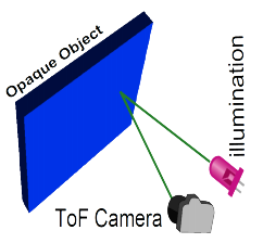
ToF cameras determine `deltat` by illuminating a scene with a strobing light source, and observing the reflected light (see left-hand figure). However, simply measuring the time delay between sending out a pulse of light and receiving a return bounce is very difficult (requiring very expensive avalanche diodes), or often even impossible with current technology (at room temperature, we quickly approach the physical limits of silicon). Instead, the conventional norm has become to measure the shift in signal phase introduced by travel time. By this approach, reflected light can be integrated over a time-period more easily achievable in modern electronics, and the time delay recovered using the equation,
`deltax = (phi/(4pi))(c/f_m)`
where `phi` is the phase delay between signals, `c` is the speed of light, and `f_m` is the modulation frequency of the signal.
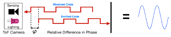
Light modulation is typically implemented with either a light-emitting or fast laser diode. To determine the phase relationship between emitted and received light pulses, the electronic shutter of an image sensor is modulated in the same pattern as the light. This effectively samples the autocorrelation waveform of the modulation signal at a zero phase-offset. To sample the entire waveform, one method is to simply sweep the phase offset of the light and image sensor modulation signals through `2pi` radians. In the case of a square-wave modulation signal, the resulting correlation waveform is a sinusoid:
Phase shifting is a perfectly valid method of constructing the correlation waveform but it does not lend well to real-time capture because of the high number of samples required to accurately reconstruct the waveform (often in excess of hundreds of samples per frame). A common method for enabling real-time capture is the “four-bin” trick. In a four-bin capture, the correlation waveform is sampled at `0`, `pi/2`, `pi` and `(3pi)/2` phase offset (thereby requiring only 4 samples per frame), and the distance calculated from,
`deltax=(c/(4pif_m))tan^-1((phi_(270^o)-phi_(90^o))/(phi_(180^o)-phi_(0^o))).`
There are a whole myriad of problems lurking beneath the surface of this basic introduction to ToF imaging. For an insight into several of the major challenges, and how we’ve gone about addressing them at MIT, take a look at our Research page.
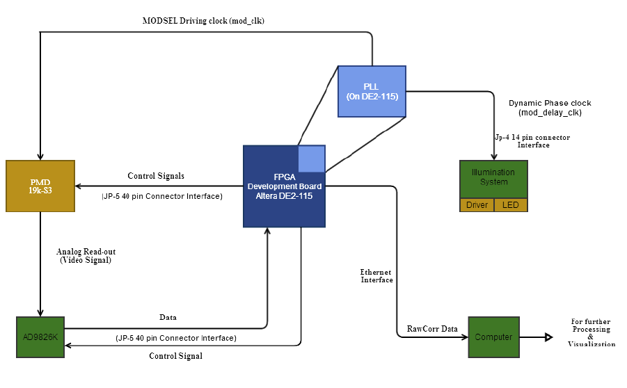
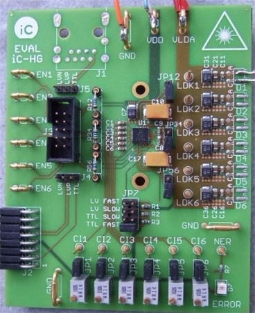
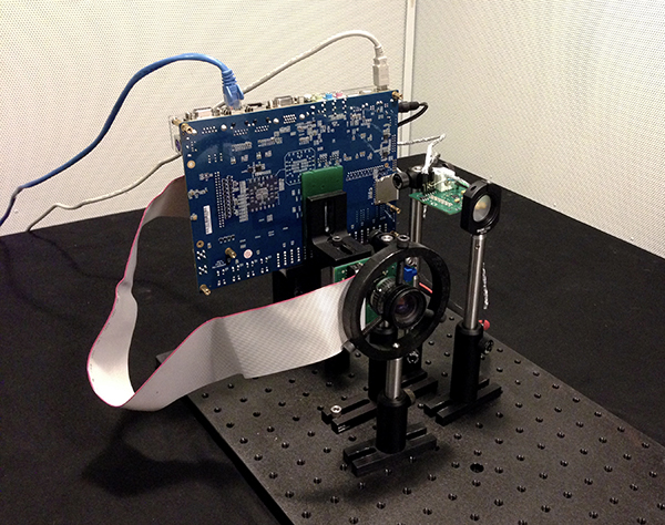
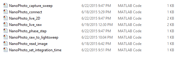
The diagram below depicts the data flow and important features of our camera. FPGA & PLL: The field programmable gate array (FPGA) acts as the camera’s central computer. It generates all configuration signals to ICs, global resets, phase-shifting of modulation signals, and controls image readout through the ADC. The FPGA also contains a soft-processor that handles higher-level functionality such as memory mapping and ethernet protocol. The phase-locked-loop (PLL) sits inside the FPGA and is responsible for generating all clock signals used by the camera and FPGA. Maintaining a strict phase relationship between modulation of the image sensor’s electronic shutter and light source is particularly important, and is also achieved inside the PLLs. PMD Image Sensor & ADC: We use a specialized ToF image sensor developed by PMD Technologies. It allows high-frequency control of the electronic shutter and fast read-out over three analog pins. Modulation of the electronic shutter is controlled by the FPGA. The analog pins are passed through an analog-to-digital converted (ADC), AD9826K, to the FPGA. The lens optics are an important design consideration not featured in the block diagram. The PMD sensor has relatively small pixel sizes so light sensitivity can often become a problem. Using a fast lens will help mitigate these effects. We currently do not recommend any specific lenses in our bill of materials, but we will in future revisions. Illumination: Illumination is provided by 3 laser diodes. Laser diodes have superior switching speeds and brightness over LEDs, which is critical to utilising the full dynamic range of the image sensor. However, care for eye safety must always be taken when using laser diodes. Computer: Image data is transferred to a host PC over ethernet (via a DHCP server). We provide acquisition drivers inside Matlab for grabbing data, controlling the camera, and processing raw data into light-sweep videos.Block diagram